How to Conduct a Thermal Simulation with CFD

We have introduced Computational Fluid Dynamics in the past, discussing what it is, its benefits, and how its application in thermal analysis for electronics devices can significantly reduce the cost of thermal testing while concurrently increasing effectiveness. The process of CFD thermal analysis includes creating a system model that allows designers to assess thermal problems within the design across various conditions. One notable advantage of CFD thermal analysis is its ability to provide results that closely resemble real-world outcomes. The analysis model considers multiple factors, including temperature dependencies of materials, properties of fluids (such as air, water, or other coolants), contact conditions, and additional structural and environmental nonlinearities.
By leveraging CFD thermal analysis, designers can directly assign thermal and flow attributes to the design geometry, facilitating optimization. This allows designers to experiment with various materials, energy, and turbulence models, enabling them to identify the optimal combination for maximum heat removal before developing. Given the prohibitive costs associated with thermal failures or design reworks based on prototype testing, incorporating comprehensive CFD thermal analysis in the early stages of the design process remains a best practice.
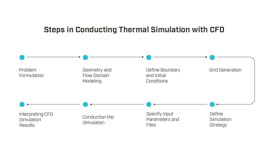
Conducting thermal simulation with CFD involves several key steps, including problem formulation, mathematical modeling, establishing boundary conditions, pre-processing with mesh generation, performing simulation using CFD software, and post-processing for result interpretation and analysis. These steps are explained in detail below, providing a comprehensive understanding of the thermal simulation process with CFD. Check out other blog posts from our thermal simulation with computational fluid dynamics (CFD) series below:
- What is Computational Fluid Dynamics?
- CFD Thermal Simulation Best Practices
- The Future of Thermal Simulation with CFD

Problem Formulation: Defining the Scope of the Analysis
The initial step of the analysis process involves formulating the problem by addressing a series of critical questions:
- What is the intended goal of the analysis?
- How can the objective be achieved most effectively?
- Which geometry elements should be included in the model?
- How can the boundary and initial conditions be established?
- What level of spatial model dimensionality is required (1-D, 2-D, 3-D, or axisymmetric)?
- How should the flow domain be represented?
- What is the appropriate temporal modeling (steady or unsteady)?
- What describes the characteristics of the viscous flow (turbulent, inviscid, or laminar)?
By formulating the problem accurately, engineers can define their models with the appropriate attributes, ensuring simulation results are free from incorrect data.
Geometry and Flow Domain Modeling
To perform an analysis, it is required to create a model of the object under consideration. This typically involves utilizing CAD software to represent the object’s geometry accurately. In some cases, certain approximations and simplifications, such as removing fastener threads, may be employed to facilitate the analysis process while maintaining reasonable accuracy. With electronic devices, particularly semiconductors, the geometry of the device can be quite simple and blocky. However, the importance of accurate geometry increases when there are heat sinks attached to electronic components with much more complicated layouts.
Simultaneously, decisions are made regarding the size of the finite flow domain within which the flow will be simulated. Certain sections of the flow domain's boundary coincide with the surfaces of the object's geometry, while other surfaces serve as free boundaries through which the flow enters or exits.
The modeling process aims to prepare the geometry and flow domain in a way that provides input for the subsequent grid generation process. This involves taking into account the structural and topological considerations necessary for generating an accurate and efficient grid. Interestingly, part of the model is the space around the model, which will need to be assigned specific properties, likely those most similar to air. While electronics cooling sometimes incorporates water or even oil, air is the most common medium that electronics reside in. The inclusion of forced-air instead of convection only, through the use of a fan, significantly increases the computational requirements of a model as that air flow is taken into account and the heat of a fan is added. Shop Same Sky's full range of ac fans and dc fans.
The designer plays a crucial role in ensuring the geometric model is free from errors or defects. Common issues to be mindful of include:
- Missing or overlapping faces
- Gaps within the model
- Unclosed geometries like edges, free faces, and vertices
After the necessary preparations, the model should be a closed solid, free from any errors mentioned above, to ensure its integrity and accuracy.
Define Boundary and Initial Conditions
Many of these steps are for general purpose analysis yet are applicable to electronics cooling and analysis as well. In this first step after modeling, as a finite flow domain is defined, it becomes necessary to set the physical conditions on the boundaries of the flow domain. The simulation process begins with an initial solution and employs an iterative approach to gradually converge towards a final flow field solution.
Grid Generation: Discretizing the Flow Domain
During the grid generation process, the flow domain is discretized into a grid by defining the grid's structure and topology. The commonly employed approach uses multi-block, structured grids, where the grid blocks may exhibit different relationships, such as contiguous, non-contiguous, or overlapping. The grid must adhere to specific grid quality standards, including orthogonality (particularly at the boundaries), relative grid spacing (with a maximum stretching value of 15% to 20%), and grid skewness.
Define the Simulation Strategy
Formulating the simulation strategy involves crucial considerations, such as adopting a suitable marching technique (space vs. time), choosing an appropriate turbulence or chemistry model, and selecting suitable algorithms. These decisions play a significant role in determining the accuracy and efficiency of the analysis process.
Specify Input Parameters and Files
An input data file plays a crucial role, as it contains a comprehensive list of input parameter values that are essential to align with the desired simulation strategy. Moreover, a grid file containing information about the grid and boundary conditions is typically needed. As part of this, heat sources can be defined, either as steady state or transient.
Conducting the Simulation
To initiate a simulation, a careful selection is made among multiple flow solvers, each designed to address a specific physical problem. Once the appropriate solver is chosen, the numerical method is selected, and boundary conditions are specified within the software. With all the necessary inputs in place, the simulation is executed on a computer or a high-performance computing (HPC) cluster. Most electronics simulations are simpler than other CFD scenarios, so these simulations are often quick, yet they sometimes require several days to complete, depending on the complexity.
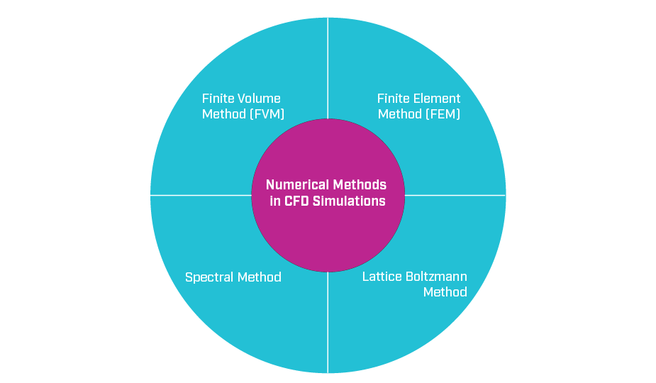
Computational Fluid Dynamics relies on various numerical methods to simulate fluid behavior using computational resources mathematically. Several commonly employed numerical methods in CFD simulations include:

Finite Volume Method (FVM)
The finite volume method in CFD involves partitioning the computational domain into a limited number of cells and solving the conservation equations (mass, momentum, and energy) for each cell. This method, based on the integral form of the governing equations, finds extensive application in commercial CFD software. The integral form of the governing equations serves as the foundation for this method, making it a prevalent choice in commercial CFD software applications.
Finite Element Method (FEM)
The finite element method is a numerical technique that approximates the solution of governing equations using basis functions defined over a finite element mesh. This method is especially effective for complex geometries and can handle moving boundary problems.
Spectral Method
The spectral method employs a truncated series of basis functions, like Chebyshev polynomials or Fourier series, to approximate the solution of the governing equations. This method is highly effective for problems that involve periodic boundary conditions, providing accurate results in such scenarios.
Lattice Boltzmann Method
The Lattice Boltzmann method is an advanced CFD computational approach that models individual particles’ behavior to simulate fluid flow. This approach is highly suitable for simulating fluid flows in porous media and accurately modeling multiphase flows, offering valuable insights into these complex scenarios.
As the field of CFD advances, numerical methods continue to evolve to tackle complex fluid flow problems. New methods are being developed to address these challenges and enhance simulation accuracy. The choice of a particular numerical method relies on the characteristics of the problem at hand and the computational capabilities provided by the CFD software. This dynamic landscape ensures that engineers have a range of options to choose from when performing CFD simulations.
Interpreting CFD Simulation Results
Following the completion of the CFD simulation, the solution yields flow variables, such as pressure and velocity, at each node of the computational grid. However, interpreting this raw data can be challenging. Hence, post-processing techniques derive integral quantities and generate graphs and plots that facilitate easier interpretation and comparison.
Post-processing aims to present the user's data and flow structures intuitively. It involves generating graphical representations with user-defined color schemes that enhance the understanding of the results. Through post-processing, users can create visually informative surface plots, such as showing thermal gradients across a semiconductor device or attached heat sink, enabling a deeper insight into flow physics and design aspects. This crucial step identifies design improvements and facilitates effective comparisons to determine the optimal solution that keeps the electronics well within the predicted temperature margin - even in the worst-case environment and in the highest power usage mode.
Summary
Moving from the concept of how Computational Fluid Dynamics works to actually implementing it accurately is not a simple jump. But by thoroughly identifying the problem, creating an accurate model, and running the simulation, useful results are created that can be interpreted and used as a foundation for design improvement in any electronics cooling scenario. Each one of these steps is equally crucial with any potential inaccuracies compiling and causing greater issues as they continue on in the process. However, carefully and effectively done, CFD is a powerful tool to reduce costs and development time. If you have any questions, Same Sky’s thermal design services and range of thermal management components are here to help.


